Web buckling, web crippling and deflection of beam
1. Web Buckling:
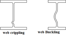
Web buckling refers to the instability or failure of the web of a steel beam under compressive loads. It occurs when the web of the beam is slender and subjected to high compressive forces, causing it to buckle out of its plane.
This phenomenon is more likely to occur in beams with thin webs or when the compressive forces are concentrated over a small area. Web buckling can significantly reduce the load-carrying capacity of a beam.
2. Web Crippling:
Web crippling is the local buckling or failure of the web of a steel beam at points of concentrated load or reaction. It occurs when the web is subjected to high bearing stresses near concentrated loads or reactions, leading to the failure of the web in those specific areas.
This type of failure is common in beams with short spans, high concentrated loads, or when the web is relatively thin. Proper design and detailing are necessary to prevent web crippling.
3. Deflection of Beam:
Deflection of a beam refers to the bending or deformation of the beam under the applied loads. When a beam is subjected to external loads, it undergoes both bending and deflection. Deflection is the displacement of any point on the beam from its original position. The deflection of a beam is influenced by factors such as the magnitude and distribution of the applied loads, the beam's material properties, its length, and the support conditions.
The IS 800 code provides guidelines and limits on deflection to ensure the structural integrity and serviceability of beams.
It's important to note that the specific design considerations, equations, and limitations related to web buckling, web crippling, and deflection of beams can be found in the Indian Standard code IS 800:2007 "General Construction in Steel - Code of Practice."
4. Bending Strength:
Bending strength, also known as flexural strength, is the maximum moment or bending force that a beam can resist before it starts to deform or fail. It is a measure of the beam's ability to resist bending stresses. IS 800 provides specifications and formulas for calculating the bending strength of steel beams based on their cross-sectional properties.
5. Shear Strength:
Shear strength refers to the maximum shear force that a beam can resist before it fails in shear. It is a measure of the beam's resistance to internal forces that cause one part of the beam to slide or shear relative to another part. IS 800 provides guidelines for determining the shear strength of steel beams based on their section properties.
6. What is plastic moment ?
Plastic moment refers to the moment capacity or resistance of a structural member, such as a beam or a column, beyond which the member enters a plastic or fully yielded state. In this state, the material undergoes significant plastic deformation without any increase in load-carrying capacity.
To understand plastic moment, let's consider a simply supported beam with a rectangular cross-section. Initially, when the beam is subjected to increasing loads, it undergoes elastic deformation, meaning it bends but returns to its original shape once the load is removed.
However, as the load increases, the bending moment in the beam also increases. At a certain point, known as the plastic moment, the extreme fibres of the beam's cross-section reach the yield strength of the material. At this moment, the material in the extreme fibres begins to undergo plastic deformation, resulting in permanent changes in shape and size even after the load is removed.
The plastic moment carrying capacity of a section refers to the maximum moment that a structural member or a section can resist before it reaches its fully yielded or plastic state. It represents the ultimate capacity of the section to withstand bending forces without any further increase in load-carrying capacity.
The plastic moment carrying capacity depends on the material properties and the geometry of the section. For a given material, the plastic moment carrying capacity of a section can be determined by considering the plastic stress distribution across the section.
In general, the plastic moment carrying capacity of a section can be calculated using the following formula:
Mp = Zp * fy
where:
Mp is the plastic moment carrying capacity of the section,
Zp is the plastic section modulus, which represents the distribution of material away from the neutral axis, and
fy is the yield strength of the material.
The plastic section modulus, Zp, is calculated based on the shape and dimensions of the section. It takes into account the location of the extreme fibres and their distance from the neutral axis of the section.


No comments:
Post a Comment