Showing posts with label steel design. Show all posts

Web buckling, web crippling and deflection of beam


 1. Web Buckling:

Web buckling refers to the instability or failure of the web of a steel beam under compressive loads. It occurs when the web of the beam is slender and subjected to high compressive forces, causing it to buckle out of its plane. 

This phenomenon is more likely to occur in beams with thin webs or when the compressive forces are concentrated over a small area. Web buckling can significantly reduce the load-carrying capacity of a beam.   


2. Web Crippling: 

Web crippling is the local buckling or failure of the web of a steel beam at points of concentrated load or reaction. It occurs when the web is subjected to high bearing stresses near concentrated loads or reactions, leading to the failure of the web in those specific areas. 


This type of failure is common in beams with short spans, high concentrated loads, or when the web is relatively thin. Proper design and detailing are necessary to prevent web crippling. 

3. Deflection of Beam: 

Deflection of a beam refers to the bending or deformation of the beam under the applied loads. When a beam is subjected to external loads, it undergoes both bending and deflection. Deflection is the displacement of any point on the beam from its original position. The deflection of a beam is influenced by factors such as the magnitude and distribution of the applied loads, the beam's material properties, its length, and the support conditions. 

The IS 800 code provides guidelines and limits on deflection to ensure the structural integrity and serviceability of beams. It's important to note that the specific design considerations, equations, and limitations related to web buckling, web crippling, and deflection of beams can be found in the Indian Standard code IS 800:2007 "General Construction in Steel - Code of Practice." 

4. Bending Strength:
Bending strength, also known as flexural strength, is the maximum moment or bending force that a beam can resist before it starts to deform or fail. It is a measure of the beam's ability to resist bending stresses. IS 800 provides specifications and formulas for calculating the bending strength of steel beams based on their cross-sectional properties.

5. Shear Strength:

Shear strength refers to the maximum shear force that a beam can resist before it fails in shear. It is a measure of the beam's resistance to internal forces that cause one part of the beam to slide or shear relative to another part. IS 800 provides guidelines for determining the shear strength of steel beams based on their section properties.

6. What is plastic moment ?

Plastic moment refers to the moment capacity or resistance of a structural member, such as a beam or a column, beyond which the member enters a plastic or fully yielded state. In this state, the material undergoes significant plastic deformation without any increase in load-carrying capacity.

To understand plastic moment, let's consider a simply supported beam with a rectangular cross-section. Initially, when the beam is subjected to increasing loads, it undergoes elastic deformation, meaning it bends but returns to its original shape once the load is removed.

However, as the load increases, the bending moment in the beam also increases. At a certain point, known as the plastic moment, the extreme fibres of the beam's cross-section reach the yield strength of the material. At this moment, the material in the extreme fibres begins to undergo plastic deformation, resulting in permanent changes in shape and size even after the load is removed.

The plastic moment carrying capacity of a section refers to the maximum moment that a structural member or a section can resist before it reaches its fully yielded or plastic state. It represents the ultimate capacity of the section to withstand bending forces without any further increase in load-carrying capacity.

The plastic moment carrying capacity depends on the material properties and the geometry of the section. For a given material, the plastic moment carrying capacity of a section can be determined by considering the plastic stress distribution across the section.

In general, the plastic moment carrying capacity of a section can be calculated using the following formula:

Mp = Zp * fy

where:

  • Mp is the plastic moment carrying capacity of the section,
  • Zp is the plastic section modulus, which represents the distribution of material away from the neutral axis, and
  • fy is the yield strength of the material.

The plastic section modulus, Zp, is calculated based on the shape and dimensions of the section. It takes into account the location of the extreme fibres and their distance from the neutral axis of the section.

ಉಕ್ಕಿನ ವಿನ್ಯಾಸಕ್ಕಾಗಿ ಬೋಲ್ಟ್ ಸಂಪರ್ಕ

ಉಕ್ಕಿನ ವಿನ್ಯಾಸ

ಬೋಲ್ಟ್ ಸಂಪರ್ಕ (Bolt connection)

ರಚನಾತ್ಮಕ ಸದಸ್ಯರನ್ನು ಸೇರಲು ಬೋಲ್ಟ್ ಸಂಪರ್ಕಗಳನ್ನು ಸಾಮಾನ್ಯವಾಗಿ ನಿರ್ಮಾಣ ಮತ್ತು ಎಂಜಿನಿಯರಿಂಗ್‌ನಲ್ಲಿ ಬಳಸಲಾಗುತ್ತದೆ. ಬೋಲ್ಟ್ ಸಂಪರ್ಕಗಳ ಕೆಲವು ಅನುಕೂಲಗಳು ಮತ್ತು ಅನಾನುಕೂಲಗಳು ಇಲ್ಲಿವೆ:

ಪ್ರಯೋಜನಗಳು:

  • ಬಹುಮುಖತೆ: ವಿವಿಧ ರೀತಿಯ ವಸ್ತುಗಳು, ಆಕಾರಗಳು ಮತ್ತು ರಚನಾತ್ಮಕ ಸದಸ್ಯರ ಗಾತ್ರಗಳನ್ನು ಸೇರಲು ಬೋಲ್ಟ್ ಸಂಪರ್ಕಗಳನ್ನು ಬಳಸಬಹುದು.
  • ಅನುಸ್ಥಾಪನೆಯ ಸುಲಭ: ಬೋಲ್ಟಿಂಗ್ ತುಲನಾತ್ಮಕವಾಗಿ ಸರಳವಾದ ಪ್ರಕ್ರಿಯೆ, ಮತ್ತು ಇದು ವಿಶೇಷ ಉಪಕರಣಗಳು ಅಥವಾ ಸಲಕರಣೆಗಳ ಅಗತ್ಯವಿರುವುದಿಲ್ಲ. ಅಗತ್ಯವಿದ್ದರೆ ಬೋಲ್ಟ್ ಸಂಪರ್ಕಗಳನ್ನು ಸುಲಭವಾಗಿ ಡಿಸ್ಅಸೆಂಬಲ್ ಮಾಡಬಹುದು ಮತ್ತು ಮರುಜೋಡಿಸಬಹುದು.
  • ಸಾಮರ್ಥ್ಯ: ಸರಿಯಾಗಿ ಸ್ಥಾಪಿಸಿದಾಗ, ಬೋಲ್ಟ್ ಸಂಪರ್ಕಗಳು ಕತ್ತರಿ, ಒತ್ತಡ ಮತ್ತು ಬಾಗುವ ಶಕ್ತಿಗಳನ್ನು ವಿರೋಧಿಸುವ ಹೆಚ್ಚಿನ ಸಾಮರ್ಥ್ಯದ ಸಂಪರ್ಕಗಳನ್ನು ಒದಗಿಸಬಹುದು.
  • ವೆಚ್ಚ-ಪರಿಣಾಮಕಾರಿ: ಬೋಲ್ಟೆಡ್ ಸಂಪರ್ಕಗಳು ವೆಲ್ಡ್ ಸಂಪರ್ಕಗಳಿಗೆ ವೆಚ್ಚ-ಪರಿಣಾಮಕಾರಿ ಪರ್ಯಾಯವಾಗಬಹುದು, ವಿಶೇಷವಾಗಿ ಸಣ್ಣ ಮತ್ತು ಸರಳವಾದ ರಚನೆಗಳಿಗೆ.
  • ತಪಾಸಣೆ: ತುಕ್ಕು, ಹಾನಿ ಅಥವಾ ಆಯಾಸದ ಚಿಹ್ನೆಗಳಿಗಾಗಿ ಬೋಲ್ಟ್ ಸಂಪರ್ಕಗಳನ್ನು ದೃಷ್ಟಿಗೋಚರವಾಗಿ ಪರಿಶೀಲಿಸಲು ಸುಲಭವಾಗಿದೆ.

ಅನಾನುಕೂಲಗಳು:

  • ಒತ್ತಡದ ಸಾಂದ್ರತೆ: ಬೋಲ್ಟ್ ಸಂಪರ್ಕಗಳು ಬೋಲ್ಟ್ ರಂಧ್ರಗಳ ಸುತ್ತಲೂ ಒತ್ತಡದ ಸಾಂದ್ರತೆಯನ್ನು ರಚಿಸಬಹುದು, ಇದು ಕಾಲಾನಂತರದಲ್ಲಿ ಆಯಾಸ ಮತ್ತು ವೈಫಲ್ಯಕ್ಕೆ ಕಾರಣವಾಗಬಹುದು.
  • ಬೋಲ್ಟ್ ಸಡಿಲಗೊಳಿಸುವಿಕೆ: ಬೋಲ್ಟ್‌ಗಳನ್ನು ಸರಿಯಾಗಿ ಬಿಗಿಗೊಳಿಸದಿದ್ದರೆ, ಅವು ಕಾಲಾನಂತರದಲ್ಲಿ ಸಡಿಲಗೊಳ್ಳಬಹುದು ಮತ್ತು ಸಂಪರ್ಕದ ಸಮಗ್ರತೆಯನ್ನು ರಾಜಿ ಮಾಡಬಹುದು.
  • ತುಕ್ಕು: ಬೋಲ್ಟ್‌ಗಳು ಮತ್ತು ಬೀಜಗಳು ಕಾಲಾನಂತರದಲ್ಲಿ ತುಕ್ಕುಗೆ ಒಳಗಾಗುತ್ತವೆ, ಇದು ಸಂಪರ್ಕವನ್ನು ದುರ್ಬಲಗೊಳಿಸುತ್ತದೆ ಮತ್ತು ಅದರ ಬಲವನ್ನು ರಾಜಿ ಮಾಡಬಹುದು.
  • ಸೌಂದರ್ಯಶಾಸ್ತ್ರ: ಬೋಲ್ಟ್ ಸಂಪರ್ಕಗಳು ಅಸಹ್ಯಕರವಾಗಿರಬಹುದು ಮತ್ತು ನೋಟವು ಮುಖ್ಯವಾದ ರಚನೆಗಳಿಗೆ ಸೂಕ್ತವಾಗಿರುವುದಿಲ್ಲ.
  • ನಿರ್ವಹಣೆ: ಬೋಲ್ಟೆಡ್ ಸಂಪರ್ಕಗಳು ಬಿಗಿಯಾಗಿ ಮತ್ತು ತುಕ್ಕು-ಮುಕ್ತವಾಗಿರುತ್ತವೆ ಎಂದು ಖಚಿತಪಡಿಸಿಕೊಳ್ಳಲು ಆವರ್ತಕ ತಪಾಸಣೆ ಮತ್ತು ನಿರ್ವಹಣೆ ಅಗತ್ಯವಿರುತ್ತದೆ.

Bolted connection| Design of steel structures

η Efficiency of joint

Find efficiency of Bolted joint ( ηJoint ).

Input of lap joints data:

The nominal size of bolts : mm.

Diameter of bolt hole : mm.

Yield strength of bolt, fyb : mm.

Ultimate strength of bolt, fub : mm.

Fe-410(E 250) plates:

Ultimate stress, fu : MPa.

yield stress, fu : MPa.

Partial safety factor, γml : MPa.

Edge distance, e : mm.

Pitch distance, p : mm.


Strength of plates in joint:

Thickness of the plate, t mm.

Width of the plate, b mm.

Number of holes in the weakest section mm.

Net area at weakest section mm2.

Design strength of plates in the joint kN.

Strength of bolts:

Total number of bolts mm.

Total number of shear planes at thread, nn mm.

Total number of shear planes at shank, ns mm.

Nominal shear strength, Vnsb kN.

Design shear strength, Vdsb kN.

Design strength in bearing:

Least value of Kb:

e/(3*do) mm.

P/(3*do)-0.25 mm.

fub/fu mm.

1.0 kN.

Least value of Kb:

Nominal strength in bearing , Vnpb: kN

Design strength in bearing, Vnpb: kN

Bolt value, V : kN

Efficiency of joints:

Area of solid plate, Dplate : mm2

Design strength of solid plate, Dplate : kN

Efficiency of the joint, ηjoint : %

Steel section connections| Design of steel structures

Steel connections

Connections in steel design.

Types of connections:

  1. Riveted connections.
  2. Bolted connections.
  3. Welded connections.

Riveted connections :

A riveted connection is a type of mechanical fastener that is used to join two or more components together. It involves inserting a metal pin (known as a rivet) through aligned holes in the components and then deforming the end of the rivet to secure it in place. Riveted connections are commonly used in the construction of bridges, buildings, and other structures, as well as in manufacturing and engineering applications. The strength of a riveted connection depends on the size and type of rivet used, as well as the material properties of the components being joined. Riveted connections are known for their durability and resistance to loosening, making them a popular choice for many applications.

Bolted connections :

A bolted connection is a type of fastener that is used to join two or more components together. It involves inserting a bolt through aligned holes in the components and securing it in place with a nut or by threading the end of the bolt. Bolted connections are commonly used in the construction of bridges, buildings, and other structures, as well as in manufacturing and engineering applications. The strength of a bolted connection depends on the size and type of bolt used, as well as the material properties of the components being joined. Bolted connections can be designed to be either tension- or shear-loaded, and are often used in applications where disassembly or adjustment is required. Additionally, bolted connections are relatively easy to install and can be designed to be reusable.

There are several types of bolted connections, including:

  • Flange connection: A type of bolted connection used to connect two or more components with a flange, typically used in pipe or ductwork systems.
  • Tension connection: A type of bolted connection designed to resist forces acting along the axis of the bolt, typically used in the construction of bridges and buildings.
  • Shear connection: A type of bolted connection designed to resist forces acting perpendicular to the axis of the bolt, typically used in the construction of bridges and buildings.
  • Slip-critical connection: A type of bolted connection designed to resist shear forces, where the bolts are tightened to a specific torque to prevent slipping between the connected components.
  • Friction-grip connection: A type of bolted connection designed to resist shear forces, where the tightness of the bolts provides friction between the connected components to transfer loads.
  • Combined tension and shear connection: A type of bolted connection that is designed to resist both tension and shear forces.
  • Each type of bolted connection has specific design considerations, and choosing the right type depends on the load conditions and the requirements of the application.

Types of bolted joints :

  • Lap joint: This type of joint is commonly used for joining two parts of the same thickness. The two parts overlap each other and are joined with bolts.
  • T-joint: A T-joint is formed when a piece of material is attached to a flat surface at a 90-degree angle. The attachment is made with bolts.
  • Butt joint: This type of joint is used to join two parts of equal thickness. The two parts are aligned end-to-end and joined with bolts.
  • Corner joint: A corner joint is used to join two parts that meet at a right angle. The two parts are joined with bolts.
  • Flange joint: A flange joint is a type of bolted joint that is used to connect two parts that have flanges. The flanges are bolted together to form a tight, leak-proof seal.
  • tension joint: A tension joint is a type of bolted joint that is designed to withstand tension forces. The bolts in this type of joint are tightened to a specific torque, which creates tension in the joint and prevents it from coming apart.
  • These are some of the most commonly used bolted joints. The specific type of joint used will depend on the application, load requirements, and design constraints.

Welded connections :

A welded connection is a type of fastener that is used to join two or more metal components together by heating and melting the surfaces to be joined and fusing them into a solid mass. Welding is a commonly used method for fabricating structures and components in the construction, manufacturing, and engineering industries. Welded connections are known for their high strength and ability to resist high loads, making them a popular choice for many applications, such as bridges, buildings, and heavy equipment. The strength of a welded connection depends on several factors, including the type of welding process used, the size and type of filler material used, and the material properties of the components being joined. However, welded connections can be more time-consuming and difficult to install compared to other fastener types

Rolled steel sections| Design of steel structures

Steel connections

Rolled steel sections.

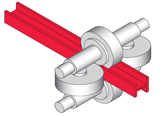
rolling steel sectio

Type of rolled steel sections:

  1. Angle sections.
  2. Channel sections.
  3. T- sections.
  4. I-sections.
  5. Round bars.
  6. Square bars.
  7. Flat bars.
  8. Corrugated sheets.
  9. Expanded metal
  10. Plates
  11. Ribbed bars (HYSD)
  12. Ribbed bars (mild steel)
  13. Thermo-mechanically treated bars
  14. Welded wire fabrics

Note: The above mentioned sections can be studied in depth by visiting following page.Click to Visit the web page!

Steel section manufacturing process :


Rolled steel Beams :

Sl.No. Short form. Full form.
1. ISJB Indian Standard Junior Beams.
2. ISLB Indian Standard Light Weight Beams.
3. ISMB Indian Standard Medium Weight Beams.
4. ISWB Indian Standard Wide Flange Beams.
5. ISHB Indian Standard Heavy Beams.

Rolled steel channels :

Sl.No. Short form. Full form.
1. ISJC Indian Standard Junior channels.
2. ISLC Indian Standard Light channels.
3. ISMC Indian Standard Medium Weight channels.

Rolled Tee beams :

Sl.No. Short form. Full form.
1. ISJT Indian Standard Junior Tee Bars.
2. ISLT Indian Standard Light Tee Bars.
3. ISNT Indian Standard Normal Tee Bars.
4. ISST Indian Standard short Tee Bars.
5. ISHT Indian Standard Wide Flange Tee Bars.

Rolled Angle :

Sl.No. Short form. Full form.
1. ISEA Indian Standard Equal angles.
2. ISUA Indian Standard Unequal angles.